In the previous lesson, we started discussing how the spanning-tree protocol constructs the loop-free network topology. We can break down the process into five steps as follows:
- Step 1. Elect the Root Bridge.
- Step 2. Select Root Ports (RPs).
- Step 3. Select Designated Ports (DPs).
- Step 4. Block Non-Designated Ports.
- Step 5. Monitor for failures.
We have already discussed the first step. In this lesson, we are going to zoom into steps 2 through 4. Let's jump in.
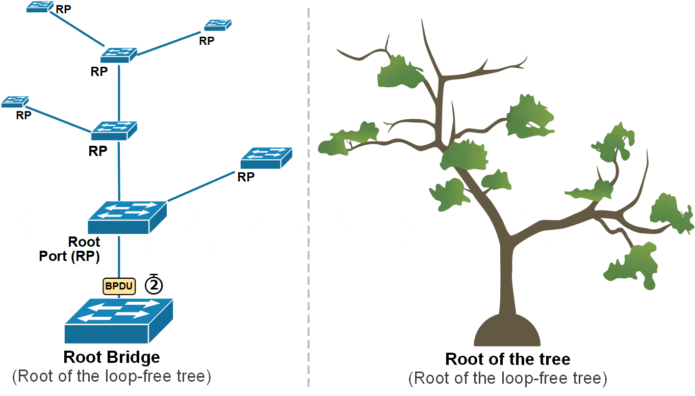
Step 1. The Root Bridge
In step 1, switches elect the root bridge. In our instance, this was SW1, as shown in the diagram below. Something important to remember about this step is that after the root bridge is elected, only the root bridge continues to generate configuration BPDUs every 2 seconds by default.

Non-root switches only forward the BPDUs they receive from the root bridge. They do not create new BPDUs themselves.
Step 2. Selecting a Root Port
The second step in the STP process happens immediately after the Root Bridge has been elected. Every switch that is not the Root Bridge must figure out which port is best for reaching the root, as shown in the diagram below.

Each switch must choose only one root port (RP), which has the lowest cost path to reach the root bridge. But what is cost in the context of STP, and what if two paths have equal cost?
Root Path Cost
Once the root bridge is selected, the STP algorithm starts calculating the best paths from every switch to the root bridge.
Switches exchange BPDUs, which include a value called the root path cost. This value shows how far the switch is from the root bridge, based on the cost of each port in the path. When a switch receives a BPDU, it adds the cost of the port where the BPDU arrived. This helps the switch calculate its own total cost to reach the root. Then, it sends out BPDUs with the new total cost downstream to its neighboring switches. The process is illustrated in the diagram below.

Notice two important facts: The root bridge's cost to reach itself is always zero (logically). Hence, he sends BPDUs with root path cost set to 0. Then, each switch adds the cost of the interface where the BPDU arrived.
Port cost depends on the speed of the port. Faster ports have lower costs. For example, 10 Gbps ports have a cost of 2, 1 Gbps ports have a cost of 4, 100 Mbps ports have a cost of 19, and 10 Mbps ports have a cost of 100. The table below lists the most common port speeds and their cost.
| Port Speed | STP Cost |
| 4 Mbps | 250 |
| 10 Mbps | 100 |
| 100 Mbps | 19 |
| 1 Gbps | 4 |
| 10 Gbps | 2 |
| 40 Gbps | 1 |
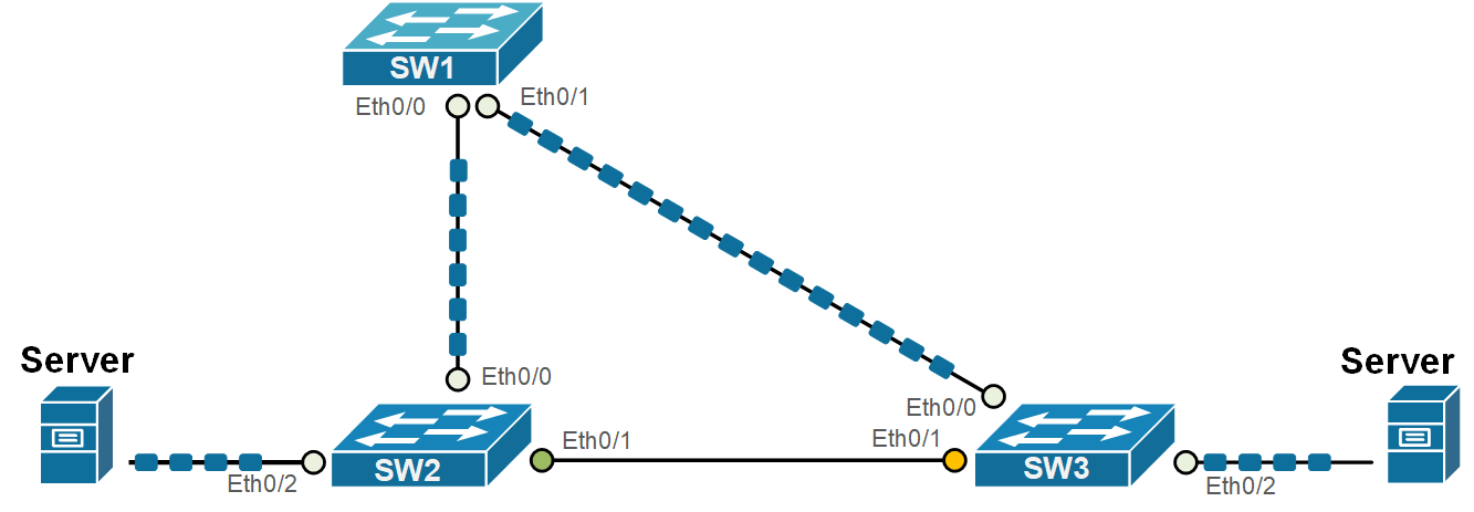
Using this process, each switch calculates the cost to reach the root bridge via each available interface. To understand the process, let's walk through a real-world example. Let's take the topology shown in the diagram below. SW1 is the root switch. Let's see how SW2 can reach the root.

SW2 can reach SW1 in two ways: directly through Ethernet 0/0 or indirectly through SW3. The cost from SW2 to SW1 directly is 100, and the cost through SW3 is 200, then SW2 picks the direct path, because 100 is lower than 200. Therefore, Ethernet0/0 becomes the Root Port (RP). We can further verify this by looking at the output below.
SW2# show spanning-tree
VLAN0001
  Spanning tree enabled protocol ieee
  Root ID    Priority    32769
             Address     0000.1111.1111
             Cost        100
             Port        1 (Ethernet0/0)
             Hello Time   2 sec  Max Age 20 sec  Forward Delay 15 sec

  Bridge ID  Priority    32769  (priority 32768 sys-id-ext 1)
             Address     0000.2222.2222
             Hello Time   2 sec  Max Age 20 sec  Forward Delay 15 sec
             Aging Time  15  sec

Interface           Role Sts Cost      Prio.Nbr Type
------------------- ---- --- --------- -------- --------------------------------
Et0/0               Root FWD 100       128.1    P2p
Et0/1               Desg FWD 100       128.2    P2p
Let's now see which port SW3 chooses as its root port. SW3 can also reach SW1 in two ways: directly through Ethernet 0/0 or indirectly through SW2, as shown in the diagram below.

The cost from SW3 to SW1 directly is 100, and the cost through SW2 is 200, then SW3 chooses the direct path via Eth0/0, because it has lower total cost (100). Therefore, Ethernet0/0 becomes the Root Port (RP). Let's verify this via the CLI.
SW3# show spanning-tree

VLAN0001
  Spanning tree enabled protocol ieee
  Root ID    Priority    32769
             Address     0000.1111.1111
             Cost        100
             Port        1 (Ethernet0/0)
             Hello Time   2 sec  Max Age 20 sec  Forward Delay 15 sec

  Bridge ID  Priority    32769  (priority 32768 sys-id-ext 1)
             Address     0000.3333.3333
             Hello Time   2 sec  Max Age 20 sec  Forward Delay 15 sec
             Aging Time  300 sec

Interface           Role Sts Cost      Prio.Nbr Type
------------------- ---- --- --------- -------- --------------------------------
Et0/0               Root FWD 100       128.1    P2p
Et0/1               Altn BLK 100       128.2    P2p
Sometimes, two or more paths have the same lowest cost. In that case, the switch uses extra rules to decide which path to pick.
Root Port Selection Logic
The root bridge keeps sending configuration BPDUs on all its interfaces. Each switch receives these BPDUs and uses them to decide which interface is the best path to the root bridge. The switch picks its RP using this order (used in case of a tie):
- Choose the port with the lowest path cost.
- If the cost is the same, choose the port that received the BPDU from a switch with the lowest BID.
- If multiple ports go to the same switch, choose the one with the lowest port priority.
- If the port priority is also the same, pick the one with the lowest port number.

Remember that every switch uses only the RP interface to reach the root. The RP can be checked using the following command.
SW2# show spanning-tree root
                                        Root    Hello Max Fwd
Vlan                   Root ID          Cost    Time  Age Dly  Root Port
---------------- -------------------- --------- ----- --- ---  ------------
VLAN0001         32769 aabb.cc00.1000       100    2   20  15  Et0/0
Step 3. Selecting Designated Ports (DPs)
Okay, let's summarize what we have discussed so far and how the Spanning Tree Protocol (STP) works:
- First, STP finds a starting point called the root bridge. This is the switch with the lowest BID and the root of the loop-free tree.
- Then, each switch selects a root port (RP) with the lowest cost to reach the root bridge.
At this point, the process has built the tree-like structure. Now, the Root Bridge starts sending configuration BPDUs every two seconds. Each switch receives those BPDUs on its root port and forwards them out all other ports, as shown in the diagram below.
However, other ports in the topology are still active, and loops can occur. To avoid these loops, STP takes one more step. It picks one designated port on each network segment. A network segment is a shared connection between two or more switches. In modern networks, a network segment in the STP context is simply a link between two switches because layer 1 hubs are no longer used, and one link cannot be shared between more than two layer 2 devices.
What is a Designated Port (DP)?
A designated port (DP) is a port that is allowed to send and receive traffic and forward BPDUs. All ports of the Root Bridge are Designated Ports (DPs) because it generates configuration BPDUs, as shown in the diagram above.
Every other non-root switch initially assumes that all its ports that are not the Root Port (RP) are designated ports (DPs). A switch doesn't know what kind of device is connected on each interface, whether it is an end device (server, PC, phone, etc.) or another switch that can cause a loop. However, if the switch receives a BPDU on a designated port, it means it comes from another switch, and it is not coming from the loop-free path, as shown on the highlighted link in the diagram below.

Every switch must receive the root's configuration BPDUs over its root port (RP) because the RP is the lowest-cost path to the root. For example, SW2 receives the root's BPDUs on Eth0/0 (the RP). SW3 receives the BPDUs on Eth0/0 (the RP).
If the switch receives configuration BPDUs on a designated port (DP), it means the port is connected to another switch via a redundant link, and there is a loop condition, as shown in the highlighted link on the diagram above. That's why STP allows only one port on the redundant link to be a designated port (to forward BPDUs).
How is a Designated Port (DP) elected on a shared segment?
Every switch knows its own path cost to the root and includes it in its BPDUs (Bridge Protocol Data Units). If a switch receives a BPDU from a neighbor with a lower cost, that neighbor becomes the designated port. The receiving switch knows that its own port is not the designated port. But if it hears only higher costs from other switches, it knows its port is the designated one.
Sometimes, two or more switches have the same path cost. STP uses a tiebreaker system with four rules, in this order, as shown in the diagram below:
- Lowest root path cost
- Lowest sender bridge ID
- Lowest sender port priority
- Lowest sender port ID
Let’s look at our example again. SW2 and SW3 receive BPDUs on non-root ports (Eth0/1). They understand that this is a redundant link between them and that this link is not part of the loop-free path. They must select a designated port for that link and block the other port to prevent loops. Using the selection algorithm shown above, they select SW2's port as the DP port and SW3's port as the alternate port, which is in a blocking state. The following diagram visualizes the end result.

An Alternative port is a port that could be used to reach the root bridge but is not currently being used because another port already provides a better (lower-cost) path. The alternate port is in a blocking state, meaning it doesn’t forward traffic or BPDUs. However, if the main path (usually the root port) fails, the alternate port can quickly take over and start forwarding frames.
SW3# show spanning-tree

VLAN0001
  Spanning tree enabled protocol ieee
  Root ID    Priority    32769
             Address     0000.1111.1111
             Cost        100
             Port        1 (Ethernet0/0)
             Hello Time   2 sec  Max Age 20 sec  Forward Delay 15 sec

  Bridge ID  Priority    32769  (priority 32768 sys-id-ext 1)
             Address     0000.2222.2222
             Hello Time   2 sec  Max Age 20 sec  Forward Delay 15 sec
             Aging Time  300 sec

Interface           Role Sts Cost      Prio.Nbr Type
------------------- ---- --- --------- -------- --------------------------------
Et0/0               Root FWD 100       128.1    P2p
Et0/1               Altn BLK 100       128.2    P2p
Et0/2               Desg FWD 100       128.3    P2p
Note that in the end result, even though all three switches are still physically connected in a triangle, STP has temporarily blocked the link between SW2 and SW3. This prevents a loop while keeping the network fully connected. Switches 2 and 3 can still send traffic to each other, but only through Switch A. For example, the two servers communicate with each other over the SW1, as shown in the diagram below.
Notice the LEDs on the switches. If those are real hardware devices, the LED on SW2's Eth0/1 port would be green but wouldn't be blinking because no real traffic is passing through. The LED on SW3's Eth0/1 port will be yellow and won't be blinking either because it is in STP blocking mode. Also, notice how the blocking port is breaking the loop and the topology is loop-free.
Putting it all together
Now, let's put it all together and summarize what we have discussed so far in the diagram shown below.
Full Content Access is for Registered Users Only (it's FREE)...
- Learn any CCNA, DevNet or Network Automation topic with animated explanation.
- We focus on simplicity. Networking tutorials and examples written in simple, understandable language for beginners.