Almost all networks in the world use Virtual Local Area Networks nowadays. In our lesson about VLANs we have learned a general rule of thumb that is:
VLAN = Broadcast Domain = Subnet
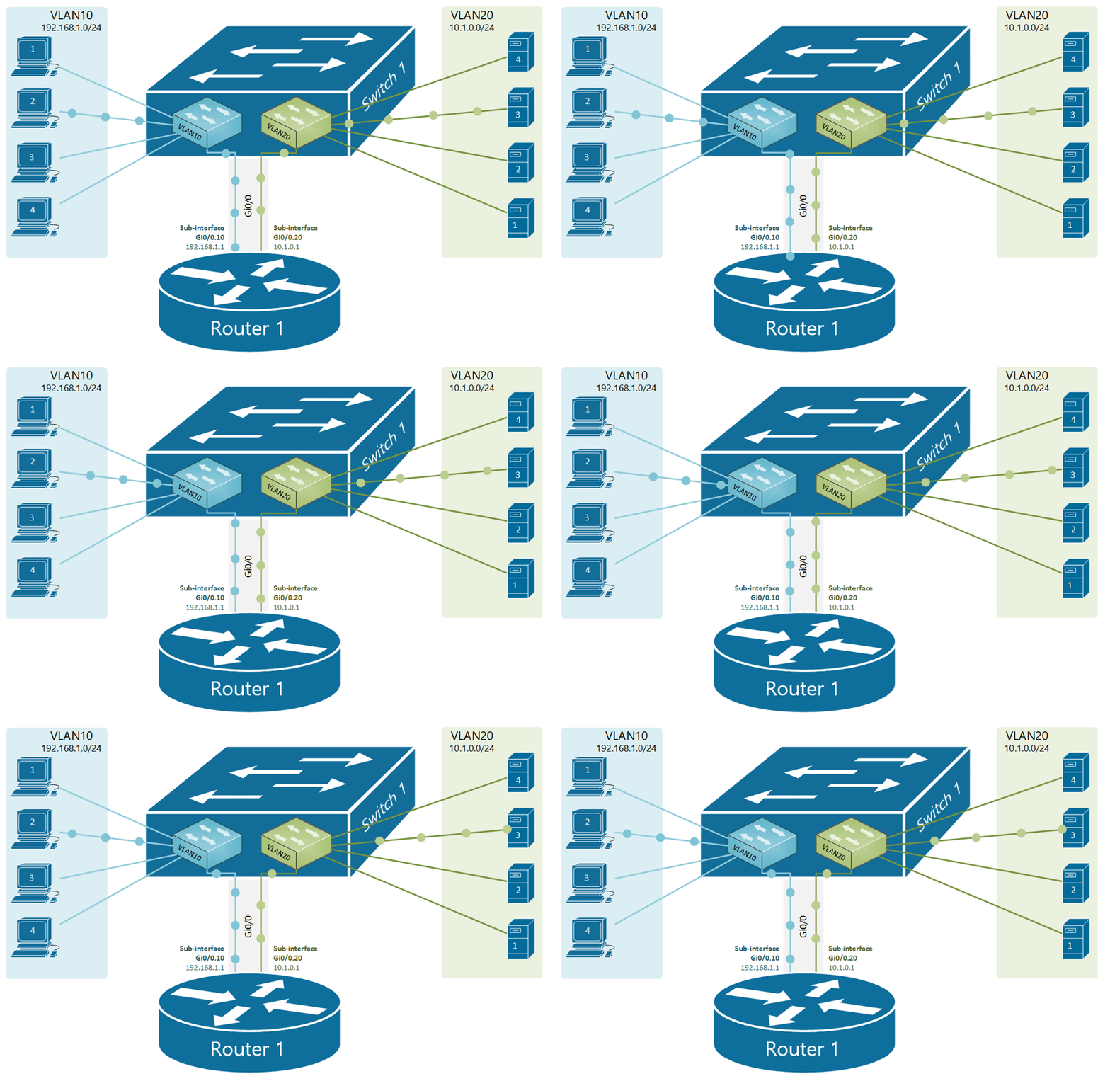
This means that if we have nodes connected in different VLANs, they most probably are part of different subnets. If we take the topology shown in Figure 1 for example, we have four clients in VLAN10 with addresses in subnet 192.168.1.0/24 and four servers in VLAN20 with addresses in 10.1.0.0/24. Therefore, the communication between the two VLANs must be handled by a device that can perform IP routing between subnets. This device must have an IP address in each network and clients need to then use these addresses as their default gateways respectively.
There are two typical devices that are used to perform routing between VLANs:
- Multilayer Switch (Layer 3 switch) - MLS switches work at both Layer 2 and Layer 3 of the OSI model. They can switch frames and perform IP routing between VLANs. We are examining this InterVLAN routing technique in our next lesson.
- Router - There are two ways to use a router as a device that performs IP routing between VLANs.
- Connecting separate router interface to each VLAN and give each interface an IP address from the respective VLAN subnet. Then it is just a regular routing between networks. We have already discussed this technique in detail in one of our previous lessons.
- Connecting a router with a single link to a switch trunk port and defining sub-interfaces for each vlan. An IP address is then configured on each sub-interface from the respective VLAN. This technique is called router-on-a-stick (ROAS) because there is only one physical link between the router and the switch as you can see in figure 1.
What is router-on-a-stick?
Router-on-a-stick (ROAS) is a technique to connect a router with a single physical link to a switch and perform IP routing between VLANs. From the switch's perspective, this physical link is configured as a trunk port allowing all VLANs that are going to be routed. From the router's perspective, this physical interface is represented as multiple virtual sub-interfaces, one for each VLAN. An IP address from each VLAN is then configured on each sub-interface and the router performs IP routing between connected networks.
Comparing this approach to the other scenario where we can use a physical interface for each VLAN. It is obviously a better more scalable technique to use a single trunk link between the switch and the router as shown in figure 1.

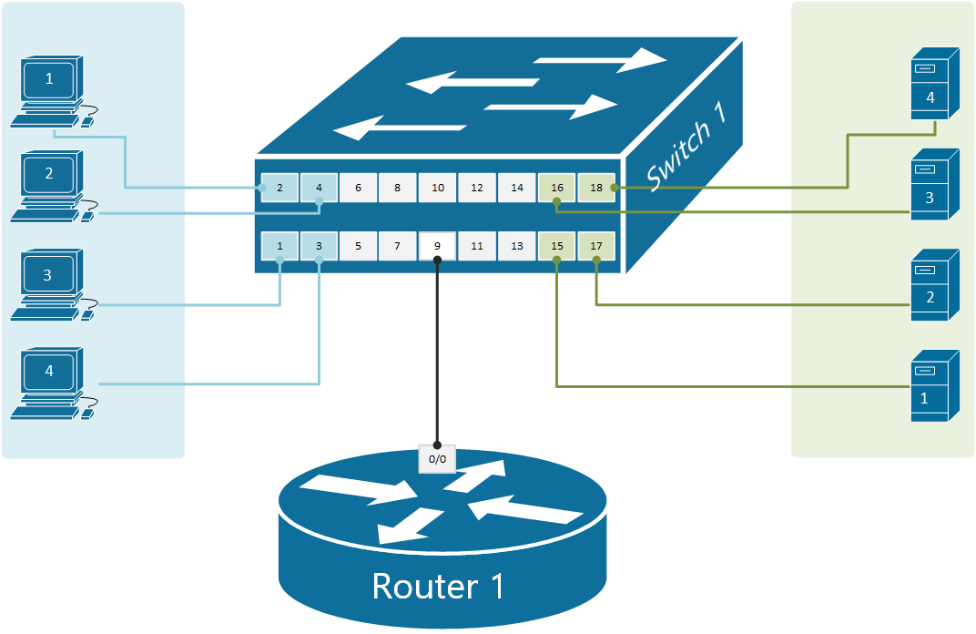
Let's look more closely at the above physical diagram. There is a single cable connecting Router1 to Switch1. From the switch's perspective, port 9 is an 802.1q trunk that sends all frames toward the router with a VLAN tag.
From the router's perspective, all frames are coming in tagged. Therefore, based on this tag the router can differentiate which incoming frames are part of which VLAN. Knowing the VLAN number of each frame, the router knows also which subnet it is part of, because VLAN = Broadcast Domain = Subnet. Having this logic in mind, we can create a virtual interface on the router that treats all frames tagged with VLAN 10 as connected to a virtual interface Gi0/0.10 and all frames tagged with VLAN20 as connected to sub-interface Gi0/0.20.
Router1(config)#interface GigabitEthernet 0/0.10
Router1(config-subif)#encapsulation dot1Q ?
  <1-4094>  IEEE 802.1Q VLAN ID
Router1(config-subif)#encapsulation dot1Q 10
We create a sub-interface using the command interface [interface-name].[sub-interface number]. This creates a virtual interface with the specified number and leads us into the sub-interface configuration mode. There we specify the VLAN ID with the command encapsulation dot1Q [vlan-id], which tells the router that when frames come in the physical interface and are tagged with this particular VLAN number, they should be handled by this sub-interface. Have in mind that the sub-interface number does not have to match the VLAN-ID and could be any random number between 1-429496729. However, the VLAN-ID under the encapsulation command must match the VLAN number on the switch.

Physical diagram
Shown in figure 1 is our physical topology for this example. Note that there is only one physical link between the switch and the router which will be used for all VLANs. Compare this topology to the one from the previous lesson, where there was a physical link for every VLAN.

Configuring the switch
Let's first start with defining the VLANs on the switch:
Switch1(config)#vlan 10
Switch1(config-vlan)#name CLIENTS
Switch1(config-vlan)#vlan 20
Switch1(config-vlan)#name SERVERS
Switch1(config-vlan)#exit
And then configure the clients' ports:
Switch1(config)#interface range fastEthernet 0/1-4
Switch1(config-if-range)#description CLIENTS
Switch1(config-if-range)#switchport mode access
Switch1(config-if-range)#switchport access vlan 10
Switch1(config-if-range)#exit

Switch1(config)#interface range fastEthernet 0/15-18
Switch1(config-if-range)#description SERVERS
Switch1(config-if-range)#switchport mode access
Switch1(config-if-range)#switchport access vlan 20
Switch1(config-if-range)#end
The last part is to configure the port where the router is connected to act as an 802.1Q trunk port.
Switch1(config)#interface fastEthernet 0/9
Switch1(config-if)#description LINK-TO-ROUTER1
Switch1(config-if)#switchport mode trunk
Switch1(config-if)#exit
Configuring the router
Let's see that the router is with default settings. It has three physical interfaces with no configuration at all currently administratively down.
Router>show ip int brief
Interface              IP-Address      OK? Method Status                Protocol
GigabitEthernet0/0     unassigned      YES unset  administratively down down
GigabitEthernet0/1     unassigned      YES unset  administratively down down
GigabitEthernet0/2     unassigned      YES unset  administratively down down
According to our physical diagram, we will have one router interface Gi0/0 connected to the switch on port 9. The first configuration step we must perform is to enable the interface. Just to remind you that - by default, all router interfaces are shut down (administratively down) and all switch interfaces are enabled. This also applies in case we have a device that has switchports (layer 2 interfaces) and router ports (layer 3 interfaces) at the same time. Layer 2 interfaces are enabled by default, layer 3 interfaces are shut down.
Router1#configure terminal
Enter configuration commands, one per line.  End with CNTL/Z.

Router1(config)#interface gigabitEthernet 0/0
Router1(config-if)#no shutdown
%LINK-5-CHANGED:Interface GigabitEthernet0/0, changed state to up
%LINEPROTO-5-UPDOWN:Line protocol on Interface GigabitEthernet0/0, changed state to up
The goal of the router-on-a-stick is to route data between the VLANs using only one physical link. However, the router needs to have an IP address/mask associated with each VLAN because VLAN = Broadcast Domain = Subnet. So to have an address in each VLAN, the router can create virtual routing interfaces associated with each VLAN. These virtual interfaces are called subinterfaces. Let's configure a sub-interface for VLAN10.
Router1(config)#interface gigabitEthernet 0/0.10
%LINK-5-CHANGED: Interface GigabitEthernet0/0.10, changed state to up
%LINEPROTO-5-UPDOWN: Line protocol on Interface GigabitEthernet0/0.10,
changed state to up

Router1(config-subif)#encapsulation dot1Q 10
Router1(config-subif)#ip address 192.168.1.1 255.255.255.0
Router1(config-subif)#exit
And one more sub-interface for VLAN20.
Router1(config-if)#interface gigabitEthernet 0/0.20
%LINK-5-CHANGED: Interface GigabitEthernet0/0.20, changed state to up
%LINEPROTO-5-UPDOWN: Line protocol on Interface GigabitEthernet0/0.20,
 changed state to up

Router1(config-subif)#encapsulation dot1Q 20
Router1(config-subif)#ip address 10.1.0.1 255.255.255.0
Router1(config-subif)#exit
Now that we have a sub-interface created for each VLAN. The router can forward data between the subnets, as shown in figure 2.

Let's look at the router's interface configuration now.
Router1#show ip int brief
Interface              IP-Address      OK? Method Status                Protocol
GigabitEthernet0/0     unassigned      YES unset  up                    up
GigabitEthernet0/0.10  192.168.1.1     YES manual up                    up
GigabitEthernet0/0.20  10.1.0.1        YES manual up                    up
GigabitEthernet0/1     unassigned      YES unset  administratively down down
GigabitEthernet0/2     unassigned      YES unset  administratively down down
Note that no IP address is configured on the physical interface Gi0/0, highlighted in yellow. All layer 3 configuration is applied under the respective sub-interface. If we now check the routing table of router1, we are going to see that it is connected to both networks (VLAN10 192.168.1.0/24 and VLAN20 10.1.0.0/24)
Router1#show ip route
Codes: L - local, C - connected, S - static, R - RIP, M - mobile, B - BGP
       D - EIGRP, EX - EIGRP external, O - OSPF, IA - OSPF inter area
       N1 - OSPF NSSA external type 1, N2 - OSPF NSSA external type 2
       E1 - OSPF external type 1, E2 - OSPF external type 2, E - EGP
       i - IS-IS, L1 - IS-IS level-1, L2 - IS-IS level-2, ia - IS-IS inter area
       * - candidate default, U - per-user static route, o - ODR
       P - periodic downloaded static route

Gateway of last resort is not set

     10.0.0.0/8 is variably subnetted, 2 subnets, 2 masks
C       10.0.1.0/24 is directly connected, GigabitEthernet0/0/0.20
L       10.0.1.1/32 is directly connected, GigabitEthernet0/0/0.20
     192.168.1.0/24 is variably subnetted, 2 subnets, 2 masks
C       192.168.1.0/24 is directly connected, GigabitEthernet0/0/0.10
L       192.168.1.1/32 is directly connected, GigabitEthernet0/0/0.10
The last verification step would be to try a ping between a client in VLAN10 and a server in VLAN20. And sure there is connectivity.
C:\>ping 10.1.0.10

Pinging 10.1.0.10 with 32 bytes of data:

Reply from 10.1.0.10: bytes=32 time<1ms TTL=127
Reply from 10.1.0.10: bytes=32 time<1ms TTL=127
Reply from 10.1.0.10: bytes=32 time<1ms TTL=127
Reply from 10.1.0.10: bytes=32 time<1ms TTL=127

Ping statistics for 10.1.0.10:
    Packets: Sent = 4, Received = 4, Lost = 0 (0% loss),
Approximate round trip times in milli-seconds:
    Minimum = 0ms, Maximum = 0ms, Average = 0ms