This lesson walks through some PIM basics using real configuration examples. Along the way, we introduce some important concepts regarding multicast on Cisco IOS-XE routers and PIM.
Notice that at the end of the page, you can download the EVE-NG files and test them yourself in your home EVE-NG virtual machine.
Lab Initial State
For this lab, we use the topology shown in the diagram below.

The lab is fully configured with IP settings and unicast routing. OSPF runs on all routers, so there is full IP reachability between the source and the receivers.
Lab Requirements
We are tasked to enable multicast in the lab topology:
- The source must be able to send multicast on group 239.1.1.1.
- The three receivers must be able to join group 239.1.1.1 and receive the multicast.
- When the source pings the group IP address 239.1.1.1, all receivers, RCV1, RCV2, and RCV3, must reply.
- PIM must operate in Dense mode.
Configuring Multicast on Cisco IOS-XE
To keep things simple and straightforward, let's break the process of enabling multicast in the network into multiple steps.
Step 1: Turning on Multicast Routing (per device)
First, let's verify that the source can actually ping each receiver. You can see that it can. Therefore, there is full IP reachability in both directions as far as unicast routing is concerned.
SOURCE# ping 10.20.1.10
Type escape sequence to abort.
Sending 5, 100-byte ICMP Echos to 10.20.1.10, timeout is 2 seconds:
!!!!!
Success rate is 100 percent (5/5), round-trip min/avg/max = 1/1/2 ms
SOURCE# ping 10.20.1.20
Type escape sequence to abort.
Sending 5, 100-byte ICMP Echos to 10.20.1.20, timeout is 2 seconds:
!!!!!
Success rate is 100 percent (5/5), round-trip min/avg/max = 1/1/2 ms
SOURCE# ping 10.20.1.30
Type escape sequence to abort.
Sending 5, 100-byte ICMP Echos to 10.20.1.30, timeout is 2 seconds:
!!!!!
Success rate is 100 percent (5/5), round-trip min/avg/max = 1/1/2 ms
Now, we can focus on the multicast part. The first important aspect of multicast in Cisco IOS and IOS-XE routers is that multicast forwarding is disabled on all devices by default. This means that a router won't forward multicast traffic between interfaces by default.
Let's verify this on the CLI on router R1. If we check the show IP multicast command on the device, we see that Multicast Routing is disabled (highlighted).
R1# show ip multicast
  Multicast Routing: disabled
  Multicast Multipath: disabled
  Multicast Route limit: No limit
  Multicast Fallback group mode: Sparse
  Number of multicast boundaries configured with filter-autorp option: 0
  MoFRR: Disabled
  Multicast Service-Reflect Capabilities:
        Unicast to Multicast
This can also be verified by checking the multicast routing table on the router. In the mroute table, the router directly says that "IP Multicast Forwarding is not enabled," as highlighted in the output below.
R1# show ip mroute
IP Multicast Routing Table
Flags: D - Dense, S - Sparse, B - Bidir Group, s - SSM Group, C - Connected,
       L - Local, P - Pruned, R - RP-bit set, F - Register flag,
       T - SPT-bit set, J - Join SPT, M - MSDP created entry, E - Extranet,
       X - Proxy Join Timer Running, A - Candidate for MSDP Advertisement,
       U - URD, I - Received Source Specific Host Report,
       Z - Multicast Tunnel, z - MDT-data group sender,
       Y - Joined MDT-data group, y - Sending to MDT-data group,

Outgoing interface flags: H - Hardware switched, A - Assert winner, p - PIM Join
                          t - LISP transit group
 Timers: Uptime/Expires
 Interface state: Interface, Next-Hop or VCD, State/Mode

IP Multicast Forwarding is not enabled.
We enable multicast routing on a Cisco device using the following command in global configuration mode.
R1# conf t
R1(config)# ip multicast-routing
R1(config)# end
R1#
We can now verify that multicast routing is enabled. The router can now forward multicast between PIM-enabled interfaces.
R1# sh ip multicast
  Multicast Routing: enabled
  Multicast Multipath: disabled
  Multicast Route limit: No limit
  Multicast Fallback group mode: Sparse
  Number of multicast boundaries configured with filter-autorp option: 0
  MoFRR: Disabled
  Multicast Service-Reflect Capabilities:
        Unicast to Multicast
We must go ahead and enable multicast routing on all routers in the topology - R1 through R6.
Once we are done, routers can now forward multicast between PIM-enabled interfaces. However, we still haven't configured PIM on any interface in the topology.
MUST REMEMBER:
- Multicast routing is disabled by default on all Cisco devices.
- It is enabled manually via a global CLI command.
- One of the most common problems people encounter with multicast is a router along the path that is not enabled to do multicast routing.
Step 2: Enabling PIM (per-interface)
Although we have already introduced PIM in the previous lesson, let's quickly touch on the most important aspects of PIM.
- PIM is independent of the unicast routing and can work alongside any protocol, including EIGRP, OSPF, ISIS, BGP, or static routes.
- PIM uses the information obtained by the unicast routing protocol to build the multicast distribution tree.
- Although PIM is called a multicast routing protocol, it is not actually a "routing protocol" because it doesn't send and receive routing updates.
- PIM is defined in the following RFCs if you want to dive into the rabbit hole:
PIM Modes
PIM can operate in three modes:
- PIM Dense Mode - uses a push model to deliver multicast.
- PIM Sparse Mode - uses a pull model to deliver multicast.
- PIM Sparse-Dense Mode - a combination of the two modes applied per group. One group can operate in dense mode, another in sparse mode.
We discuss each mode in greater detail in the next lessons. For now, let's use PIM Dense mode as the simplest one.
PIM Versions
PIM has evolved through two versions. Currently, version 2 is pretty much used everywhere, while version 1 is considered legacy and not used at all. However, PIM v1 and v2 can coexist in the same network, even on the same device/interface.
The primary difference between version 1 and version 2 is the packet format.
- PIMv1 utilizes the Internet Group Management Protocol (IGMP) packet format.
- PIMv2 has its own distinct IP protocol number (103) and packet structure.
- With PIMv2, the operational mode (dense or sparse) is a group's property instead of an interface, as in version 1.
Throughout this course, we only used PIMv2, which is currently the standard in every network. Most vendors and platforms already discontinued supporting PIMv1.
PIM Neighbors
PIM is enabled per interface, as shown in the diagram below.

Notice what happens when we enable PIM Dense mode on the e0/0 interfaces of routers R1 and R2 - they become neighbors.
R1# conf t
R1(config)# int e0/0
R1(config-if)# ip pim dense-mode
R1(config-if)# end
*Jun 28 20:22:26.586: %PIM-5-DRCHG: DR change from neighbor 0.0.0.0 to 10.10.1.252 on interface Ethernet0/0
*Jun 28 20:22:35.401: %PIM-5-NBRCHG: neighbor 10.10.1.253 UP on interface Ethernet0/0
*Jun 28 20:22:35.403: %PIM-5-DRCHG: DR change from neighbor 10.10.1.252 to 10.10.1.253 on interface Ethernet0/0
R1#
When we enable PIM on an interface, the PIM process immediately starts sending PIM Hello messages on the segment to the link-local multicast address
224.0.0.13, as shown in the screenshot below.
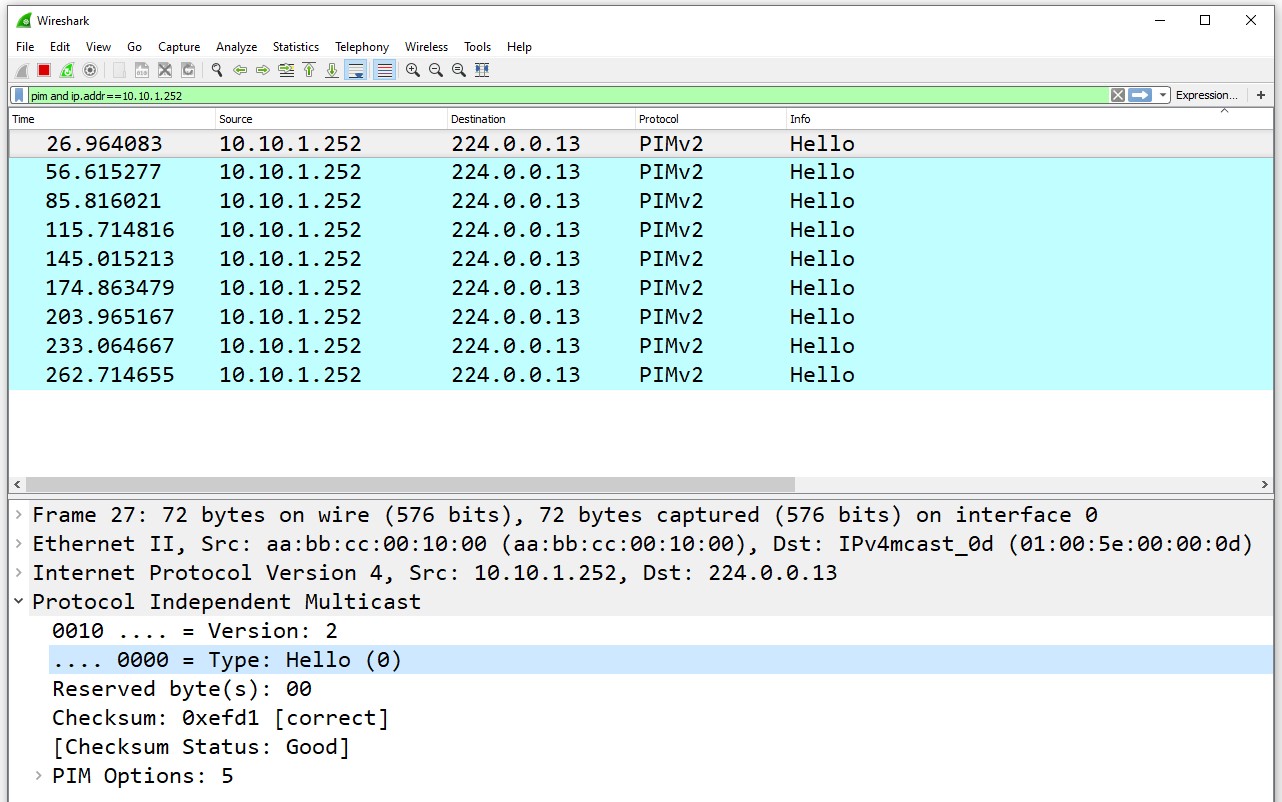
The messages are sent every 30 seconds with a hold timer of 3.5 hellos (105 seconds). When another router has a PIM-enabled interface on the same segment, the two routers hear each other and establish PIM adjacency. We check a router's adjacencies using the following command.
R1# sh ip pim neighbor
PIM Neighbor Table
Mode: B - Bidir Capable, DR - Designated Router, N - Default DR Priority,
      P - Proxy Capable, S - State Refresh Capable, G - GenID Capable,
      L - DR Load-balancing Capable
Neighbor          Interface                Uptime/Expires    Ver   DR
Address                                                            Prio/Mode
10.10.1.253       Ethernet0/0              00:00:15/00:01:29 v2    1 / DR S P G
Additionally, we can check a router's PIM-enabled interfaces and see if any adjacencies are formed on each interface. See the Nbr Count column.
R1# sh ip pim interface
Address          Interface                Ver/   Nbr    Query  DR         DR
                                          Mode   Count  Intvl  Prior
10.10.1.252      Ethernet0/0              v2/D   1      30     1          10.10.1.253
Now, let's enable PIM Dense mode on all router interfaces in the topology, as shown in the diagram below. We simply configure the command ip pim dense-mode on every interface.

At this point, we have multicast routing enabled on every router and PIM enabled on every interface. Now, we must be able to send and receive multicast, right? Well, there is one more mandatory step to go through.
MUST REMEMBER:
- PIM is disabled by default on all interfaces on a Cisco device.
- It is enabled manually via an interface-level CLI command.
- One of the most common problems people encounter with multicast is an interface along the path that is not PIM-enabled.
- Don't forget to enable PIM on the interface that connects to the source.
- Don't forget to enable PIM on the interface that connects to the receivers.
Step 3. Configuring IGMP Group Membership
Although we enabled multicast routing on all routers and enabled PIM on all router interfaces, if we try to ping the group IP address 239.1.1.1 from the source, nothing happens.
SOURCE# ping 239.1.1.1 re 10
Type escape sequence to abort.
Sending 10, 100-byte ICMP Echos to 239.1.1.1, timeout is 2 seconds:
..........
That's because there are no interested receivers at the moment!
PIM builds and maintains multicast distribution trees based on receiver-initiated membership. Without interested receivers, there is no point in sending the multicast stream anywhere. Let's configure the IGMP settings on the receivers so that they join the 239.1.1.1 multicast group. Notice that we also use the IOL-XE image for the routers and hosts. So, the source and the receiver are simple Cisco IOS-XE routers.
Let's configure the receivers to join the multicast group.

On each receiver, we use the following command to Join the interface to the multicast group address.
RCV1# conf t
RCV1(config)# int e0/0
RCV1(config-if)# ip igmp join-group 239.1.1.1
RCV1(config-if)# end
We must configure this on every receiver. When we are done, we can now try to ping the multicast group address from the source.
SOURCE# ping 239.1.1.1 re 3
Type escape sequence to abort.
Sending 100, 100-byte ICMP Echos to 239.1.1.1, timeout is 2 seconds:
Reply to request 0 from 10.20.1.30, 34 ms
Reply to request 0 from 10.20.1.30, 39 ms
Reply to request 0 from 10.20.1.30, 39 ms
Reply to request 0 from 10.20.1.20, 39 ms
Reply to request 0 from 10.20.1.20, 39 ms
Reply to request 0 from 10.20.1.10, 39 ms
Reply to request 0 from 10.20.1.10, 39 ms
Reply to request 0 from 10.20.1.30, 34 ms
Reply to request 0 from 10.20.1.20, 34 ms
Reply to request 0 from 10.20.1.20, 34 ms
Reply to request 0 from 10.20.1.10, 34 ms
Reply to request 0 from 10.20.1.10, 34 ms
Reply to request 1 from 10.20.1.20, 2 ms
Reply to request 1 from 10.20.1.10, 2 ms
Reply to request 1 from 10.20.1.30, 2 ms
Reply to request 2 from 10.20.1.10, 2 ms
Reply to request 2 from 10.20.1.30, 2 ms
Reply to request 2 from 10.20.1.20, 2 ms
Reply to request 3 from 10.20.1.10, 2 ms
Reply to request 3 from 10.20.1.30, 2 ms
Reply to request 3 from 10.20.1.20, 2 ms
You can see that receivers now reply to the ICMP requests. Therefore, they successfully receive the multicast. We have a multicast-enabled network where sources can transmit multicast to different group addresses, and receivers can join and get the traffic.
If you are wondering why the first ping gets 4 replies from each receiver (in blue), that's a characteristic of PIM Dense mode that we discuss in the next lesson (see the part about packet duplication here). Basically, the first ICMP request that the source sends to 239.1.1.1 gets replicated multiple times while PIM builds the SPT. This results in each host receiving four copies of the ICMP Request and replying back four times. Anyway, let's not focus on this now; you will see why it happens in our lesson on Dense mode.
PIM States
The following simple diagram visualizes some important multicast fundamentals you must remember.
- Multicast flows in the direction from the source to the receiver.
- The multicast distribution tree is built in the direction from the receiver to the source.
- A general rule of thumb is to start troubleshooting in the direction from the receiver to the source.
- Notice that there is no ECMP. Only one FHR and one LHR router participate in the data plane.

Okay, but we have two routers, R5 and R6, connected to the segment where receivers are connected (see Figure 4 for example). Which router handles the data plane for that segment?
Let's check the multicast routing tables of R5 and R6 and see what happens. Let's first run the show ip mroute 239.1.1.1 command on R5.
R5# sh ip mroute 239.1.1.1
IP Multicast Routing Table
Flags: D - Dense, S - Sparse, B - Bidir Group, s - SSM Group, C - Connected,
       L - Local, P - Pruned, R - RP-bit set, F - Register flag,
       T - SPT-bit set, J - Join SPT, M - MSDP created entry, E - Extranet,
       X - Proxy Join Timer Running, A - Candidate for MSDP Advertisement,
       U - URD, I - Received Source Specific Host Report,
       Z - Multicast Tunnel, z - MDT-data group sender,
       Y - Joined MDT-data group, y - Sending to MDT-data group,
       G - Received BGP C-Mroute, g - Sent BGP C-Mroute,
       N - Received BGP Shared-Tree Prune, n - BGP C-Mroute suppressed,
       Q - Received BGP S-A Route, q - Sent BGP S-A Route,
       V - RD & Vector, v - Vector, p - PIM Joins on route,
       x - VxLAN group, c - PFP-SA cache created entry,
       * - determined by Assert, # - iif-starg configured on rpf intf,
       e - encap-helper tunnel flag, l - LISP decap ref count contributor
Outgoing interface flags: H - Hardware switched, A - Assert winner, p - PIM Join
                          t - LISP transit group
 Timers: Uptime/Expires
 Interface state: Interface, Next-Hop or VCD, State/Mode
(*, 239.1.1.1), 07:01:02/stopped, RP 0.0.0.0, flags: DC
  Incoming interface: Null, RPF nbr 0.0.0.0
  Outgoing interface list:
    Ethernet0/1, Forward/Dense, 07:01:02/stopped, flags:
    Ethernet0/0, Forward/Dense, 07:01:02/stopped, flags:
(10.10.1.1, 239.1.1.1), 00:06:44/00:00:09, flags: PT
  Incoming interface: Ethernet0/1, RPF nbr 10.1.3.2
  Outgoing interface list:
    Ethernet0/0, Prune/Dense, 00:00:48/00:02:11, flags:
First, notice the (*, G) entry - (*, 239.1.1.1). It has the flags D and C:
- D means that this group runs in PIM Dense mode. Remember that PIM version 2's operational mode (dense or sparse) is per group.
- C means that there are directly connected interested receivers.
Secondly, notice the (S, G) entry - (10.10.1.1, 239.1.1.1). It has the flags P and T:
- T means that the SPT bit is set, meaning the router has moved the flow to the source path tree (SPT).
- P means Pruned. The multicast group state has been pruned by PIM. Typically, this means that no interested receivers are connected to the router (and the router doesn't want the multicast), or another router serves the segment with interested receivers. In our example, it is the latter.
The checks conclude that router R5 does not participate in the data plane since it has pruned the (S, G) state (it has the flag P).
Now, let's check the multicast routing table of R6.
R6# sh ip mroute 239.1.1.1
IP Multicast Routing Table
Flags: D - Dense, S - Sparse, B - Bidir Group, s - SSM Group, C - Connected,
       L - Local, P - Pruned, R - RP-bit set, F - Register flag,
       T - SPT-bit set, J - Join SPT, M - MSDP created entry, E - Extranet,
       X - Proxy Join Timer Running, A - Candidate for MSDP Advertisement,
       U - URD, I - Received Source Specific Host Report,
       Z - Multicast Tunnel, z - MDT-data group sender,
       Y - Joined MDT-data group, y - Sending to MDT-data group,
       G - Received BGP C-Mroute, g - Sent BGP C-Mroute,
       N - Received BGP Shared-Tree Prune, n - BGP C-Mroute suppressed,
       Q - Received BGP S-A Route, q - Sent BGP S-A Route,
       V - RD & Vector, v - Vector, p - PIM Joins on route,
       x - VxLAN group, c - PFP-SA cache created entry,
       * - determined by Assert, # - iif-starg configured on rpf intf,
       e - encap-helper tunnel flag, l - LISP decap ref count contributor
Outgoing interface flags: H - Hardware switched, A - Assert winner, p - PIM Join
                          t - LISP transit group
 Timers: Uptime/Expires
 Interface state: Interface, Next-Hop or VCD, State/Mode
(*, 239.1.1.1), 07:17:42/stopped, RP 0.0.0.0, flags: DC
  Incoming interface: Null, RPF nbr 0.0.0.0
  Outgoing interface list:
    Ethernet0/1, Forward/Dense, 07:17:42/stopped, flags:
    Ethernet0/0, Forward/Dense, 07:17:42/stopped, flags:
(10.10.1.1, 239.1.1.1), 00:00:03/00:02:56, flags: T
  Incoming interface: Ethernet0/1, RPF nbr 10.1.3.2
  Outgoing interface list:
    Ethernet0/0, Forward/Dense, 00:00:03/stopped, flags: A
First, notice the (*, G) entry - (*, 239.1.1.1). It has the flags D and C:
- D means that this group runs in PIM Dense mode.
- C means that there are directly connected interested receivers.
Secondly, notice the (S, G) entry - (10.10.1.1, 239.1.1.1). It has only the flag T:
- T means the SPT bit is set, meaning the router has moved the flow to the source path tree (SPT).
- Notice that the incoming interface is Ethernet0/1, meaning the multicast from 10.10.1.1 on group 239.1.1.1 comes on e0/1.
- The Outgoing Interface List (OIL) has one interface - e0/0, meaning the router replicates the multicast packets on this interface. This is the segment where the receivers are connected.
From the mroute table, we can conclude that R6 is the router that forwards multicast traffic into the receivers' segment. This can be further verified by looking at the mfib table, as shown in the following output.
R6# sh ip mfib 239.1.1.1
Entry Flags:    C - Directly Connected, S - Signal, IA - Inherit A flag,
                ET - Data Rate Exceeds Threshold, K - Keepalive
                DDE - Data Driven Event, HW - Hardware Installed
                ME - MoFRR ECMP entry, MNE - MoFRR Non-ECMP entry, MP - MFIB
                MoFRR Primary, RP - MRIB MoFRR Primary, P - MoFRR Primary
                MS  - MoFRR  Entry in Sync, MC - MoFRR entry in MoFRR Client,
                e   - Encap helper tunnel flag.
I/O Item Flags: IC - Internal Copy, NP - Not platform switched,
                NS - Negate Signalling, SP - Signal Present,
                A - Accept, F - Forward, RA - MRIB Accept, RF - MRIB Forward,
                MA - MFIB Accept, A2 - Accept backup,
                RA2 - MRIB Accept backup, MA2 - MFIB Accept backup
Forwarding Counts: Pkt Count/Pkts per second/Avg Pkt Size/Kbits per second
Other counts:      Total/RPF failed/Other drops
I/O Item Counts:   HW Pkt Count/FS Pkt Count/PS Pkt Count   Egress Rate in pps
Default
 (*,239.1.1.1) Flags: C
   SW Forwarding: 0/0/0/0, Other: 0/0/0
   Ethernet0/1 Flags: F NS
     Pkts: 0/0/0    Rate: 0 pps
   Ethernet0/0 Flags: F NS
     Pkts: 0/0/0    Rate: 0 pps
 (10.10.1.1,239.1.1.1) Flags:
   SW Forwarding: 107/0/100/0, Other: 2/2/0
   Ethernet0/1 Flags: A
   Ethernet0/0 Flags: F
     Pkts: 0/305/2    Rate: 0 pps
You can see that R6 forwards multicast traffic for (10.10.1.1, 239.1.1.1)—Eth0/0 has the flag F, which stands for Forwarding. If you execute the command multiple times, the counter must increase (if the source is still pining the group address 239.1.1.1).
Full Content Access is for Registered Users Only (it's FREE)...
- Learn any CCNA, DevNet or Network Automation topic with animated explanation.
- We focus on simplicity. Networking tutorials and examples written in simple, understandable language for beginners.